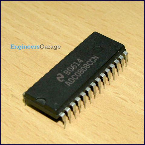
ADC0808LCN: 28 PIN 8 BIT A/D CONVERTER WITH 8-CHANNEL ANALOG
By --
SKU : 0
| Pin No | Function | Name |
| 1 | Analog input pins | IN3 |
| 2 | IN4 | |
| 3 | IN5 | |
| 4 | IN6 | |
| 5 | IN7 | |
| 6 | Start conversion; input pin; a low to high pulse is given | SC |
| 7 | End of conversion; output pin; goes low when the conversion is over | EOC |
| 8 | Digital output bit 4 | D3 |
| 9 | Input pin; a low to high pulse brings data to output pins from the internal registers at end of conversion | Output enable |
| 10 | Clock input; to provide external clock | Clock input |
| 11 | Supply voltage; 5V | Vcc |
| 12 | Positive reference voltage | Vref(+) |
| 13 | Ground ()v) | GND |
| 14 | Digital output bit | D1 |
| 15 | D2 | |
| 16 | Negative reference voltage | Vref(-) |
| 17 | Digital output bits | D0 |
| 18 | D4 | |
| 19 | D5 | |
| 20 | D6 | |
| 21 | D7 | |
| 22 | Address latch enable; Input pin; low to high pulse is required to latch in the address | ALE |
| 23 | Address lines | AddressC |
| 24 | AddressB | |
| 25 | AddressA | |
| 26 | Analog inputs | IN0 |
| 27 | IN1 | |
| 28 | IN2 |